Technical reference · English
Electrical protection design for Class II medical places
Equipment categories and medical settings
The categories of protection against electric shock of equipment and the grouping of medical premises relate to different objects. Site grouping and circuit configuration should be combined with diagnostic and treatment activities, equipment usage and project design to meet applicable requirements respectively.
Equipment classification:
Class I equipment: Equipment whose protection against electric shock not only relies on basic insulation, but also provides additional safety precautions in connection with the protective earth conductor of the fixed wiring so that the accessible metal parts are not live even when the basic insulation fails.
Class II equipment: Equipment whose protection against electric shock not only relies on basic insulation, but also has additional safety protection measures such as double insulation and reinforced insulation, but has no protective earthing measures and does not depend on the installation conditions.
Contact parts:
Parts of medical electrical equipment which, in normal use:
-The device requires physical contact with the patient in order to perform its function
-Available to bring it into contact with the patient
-Needs to be touched by patient
The effect of electric current passing through the human body
Patients may form contact paths with electrical systems through contact parts of medical equipment. Therefore, medical facilities need to design corresponding protection based on diagnosis and treatment activities and risks.
Human body impedance is affected by many factors such as skin condition, contact conditions, environmental humidity, etc. A single human body current or impedance value cannot be regarded as a safe limit.
Electrical design for Class II medical facilities
Medical IT system
Insulation monitor
Medical IT systems must be powered by medical isolation transformers and should be equipped with a long-term insulation monitor.
Selection of an insulation monitor involves applicable requirements such as IEC 61557-8. The points below are design considerations for this solution; confirm specific values against the applicable standard edition and selected model:
-AC internal impedance should be at least 100 kΩ
-Test voltage should not be greater than 25V d.c. or a.c.
-The peak value of the injected current should not be greater than 1 mA even under fault conditions
-When the insulation resistance drops to 50 KΩ, an indication signal should be issued and test equipment should also be provided
-It is strictly forbidden to disconnect the insulation monitor.
Isolation transformer
Isolation-transformer design involves applicable requirements such as IEC 60364-7-710 and IEC 61558-2-15. Key considerations include installation conditions, output voltage, capacity, insulation and shielding:
-The transformer should be installed within the medical facility or immediately outside the medical facility
- The rated secondary voltage Un of the transformer should not exceed 250 V AC
-The transformer must comply with IEC61558-2-15 standard.
In addition, the following requirements should be met:
The isolation transformer should pay attention to the leakage current under no-load state and rated conditions. The specific limit should be determined by the applicable standards and model specifications.
- Medical IT systems for mobile and fixed equipment should use single-phase transformers with a rated output capacity of not less than 0.5 kVA but not exceeding 10 kVA
- If it is also necessary to supply power to three-phase loads through the IT system, a separate three-phase transformer should be used to supply power, and the output line voltage should not exceed 250 V.
-Double or reinforced insulated windings must be used
-The metal shielding layer between windings needs to be grounded
-Short circuit voltage shall not exceed 3%
- No-load primary current shall not exceed 3%
-The peak current shall not be greater than 12 times the rated current
The determination of the patient area should take into account the likely location of the patient, contact parts and equipment, as well as the range of movement of portable or multifunctional equipment.
Patient areas should be determined based on diagnostic and treatment activities, patient location, and the range to which equipment may be moved. Protective grounding and auxiliary equipotential bonding should be configured in accordance with applicable standards and project design, and should not be based on reducing connection points or reducing costs.
Electrical system implementation for Class 2 medical locations
The design of electrical installations in medical facilities needs to take into account the clinical activities, site groupings and actual loads. Corresponding requirements apply to power supply devices and medical electrical equipment in medical places respectively, and site installation standards cannot be regarded as product standards for all medical equipment.
- Medical electrical equipment located above the surface and less than 2.5 meters high, or with access to patient areas;
- Sockets (except power supplies for electrical equipment with a capacity higher than 5 kVA and radioactive inspection equipment).
In fact, medical IT systems can achieve:
- Limit indirect contact currents generated by contact voltage;
-Reduce leakage current;
-Ensure continuity of power supply in the event of a first ground fault in the equipment.
The medical IT power distribution system diagram is as follows:
Safe power supply settings for Class II locations:
Dual power cabinet
PC-level automatic switching dual power supply
UPS and battery time
Decentralized configuration avoids centralized failure points
Single phase 10kVA capacity
30 minutes backup power storage
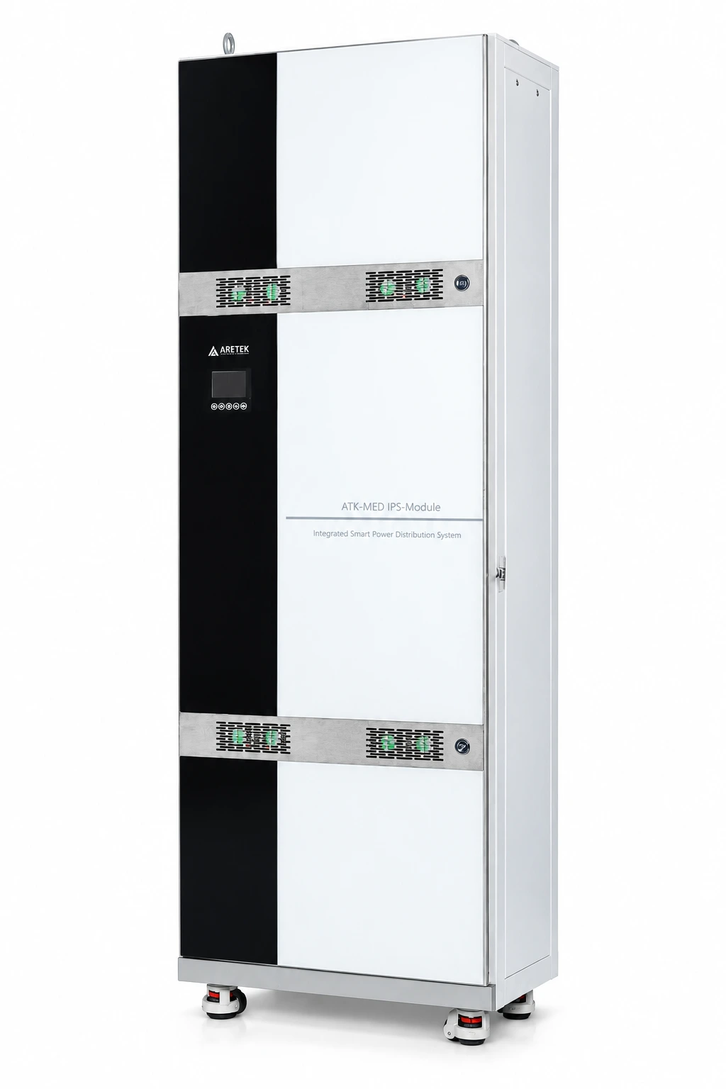
IT isolated power system cabinet
3.15kVA~10kVA system capacity
IT and TN power distribution systems
The modular power distribution method is used to meet the installation space and environmental needs of key places such as surgery and ICU.
Dual power supply switching, UPS backup time and power distribution capacity should be based on the current selection information and project requirements.