Technical reference · English
Introduction: Residual Current Monitoring (RCM) continuously detects the vector sum of the currents of each live conductor in the loop to identify insulation degradation, ground faults and abnormal leakage currents, providing continuous monitoring and early warning for electrical systems.
01What is residual current monitoring (RCM)
RCM is a device that continuously measures and monitors residual current and fault current. When measuring, all live conductors of the monitored circuit should pass through the current sensor together, and the PE protective conductors should not pass through the sensor.
When the system is operating normally and there is no leakage fault, the vector sum of the currents in each conductor is close to zero; when the current is lost through the ground path, the sensor will detect the current difference, and the RCM measurement system will record, calculate and output alarm information accordingly.
Figure 1 Schematic diagram of residual current monitoring principle
02Why continuous monitoring is needed
With the extensive application of nonlinear loads, harmonic currents in the system continue to increase, and the DC component in the load current may also reduce the sensitivity of traditional protection methods. Continuous monitoring helps detect anomalies before they develop into downtime or equipment damage.
The TN-S system can focus on:
Whether the connection between neutral conductor N and protective conductor PE complies with the design of the power supply system;
Whether there are abnormal stray currents in the system;
Neutral line third harmonic and overload risk;
The changing trend of load current and residual current of each circuit.
Figure 2: Residual current monitoring application diagram
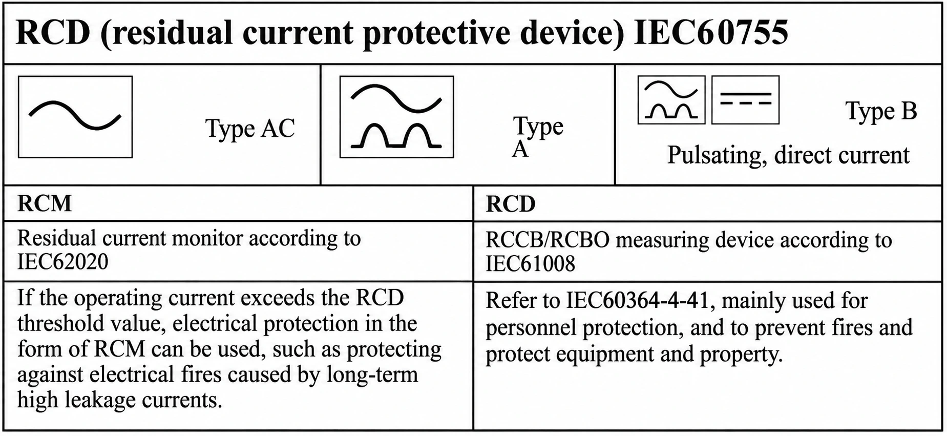
03AC type, A type and B type
For residual current monitoring, the appropriate type needs to be selected based on the load waveform and DC component characteristics. Common types include AC type, A type and B type. In addition to monitoring power frequency AC and pulsating DC, Type B can also identify smooth DC fault currents. It is especially suitable for places with a large number of power electronic equipment such as industrial frequency converters and drives.
The measurement method, identifiable waveform and frequency range of the monitoring device should be checked separately. The true RMS measurement capability and applicable range of different current types are subject to the technical description of the specific model.
04 Functional differences between RCM and RCD
RCM|Continuous monitoring and alarming
Main functions: Continuously measure, record and issue alarms.
Typical goals: Early detection of insulation deterioration to support continuous operation and maintenance decisions.
RCD|Protection action when conditions are met
Main function: Execute protective action when action conditions are met.
Typical objectives: Provide personal, equipment or fire protection under fault conditions.
05Common reference thresholds
30 mA is commonly used in scenarios related to personnel protection
300 mA is commonly used in fire protection related scenarios
Tip: The actual alarm threshold, action time and protection scheme should be determined based on applicable standards, system grounding methods, equipment inherent leakage current and project risk assessment.
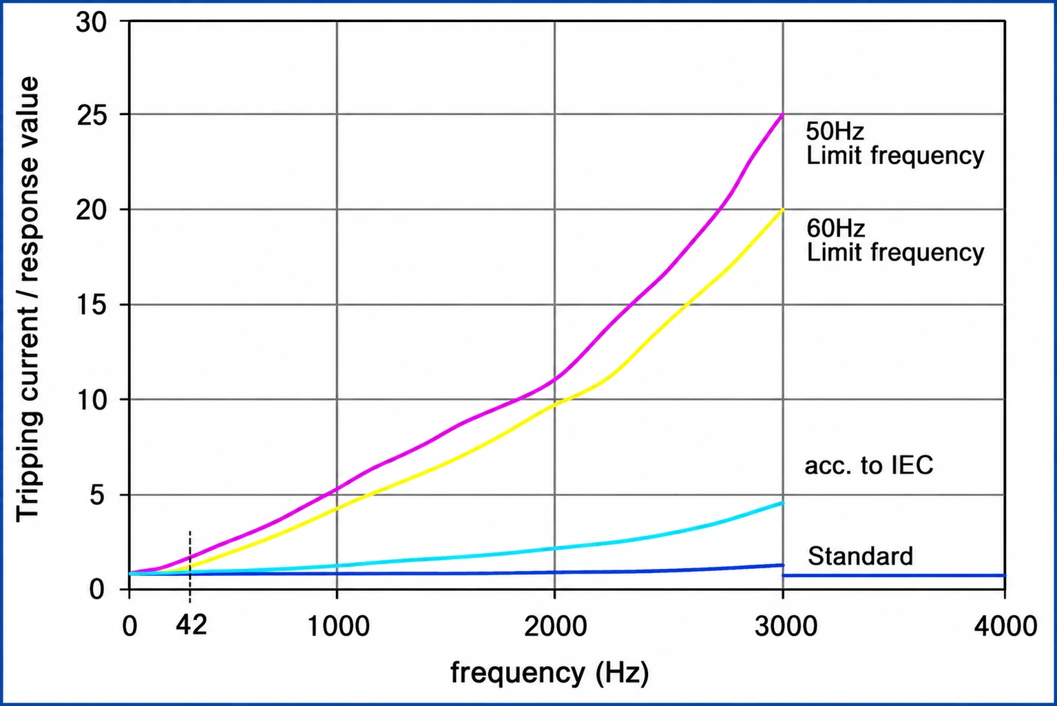
Figure 3: Schematic diagram of the relationship between frequency and operating current
06Typical application scenarios
Systems with concentrated industrial inverters, drives and power electronic equipment;
Residual current and fault current monitoring of TN, TT, IT and other grounding systems;
Continuous operation sites where production interruption due to unnecessary actions is not expected;
Critical equipment requiring insulation deterioration trend analysis and preventive maintenance.
07 Summary
By continuously monitoring the residual current and fault current in the grounding system, RCM provides timely abnormal alarms without directly cutting off the power supply, helping to reduce unplanned shutdowns, equipment damage and subsequent maintenance costs. RCM and RCD have different functions and should be reasonably coordinated based on system risks and protection goals.