Technical reference · English
Medical Class 1 TN loop and Class 2 IT system monitoring solutions
Establish hierarchical monitoring, on-site alarm and centralized communication capabilities for medical sites of different levels to help operation and maintenance personnel identify insulation, residual current, load and temperature rise abnormalities earlier.
Monitoring is configured according to the classification of medical sites
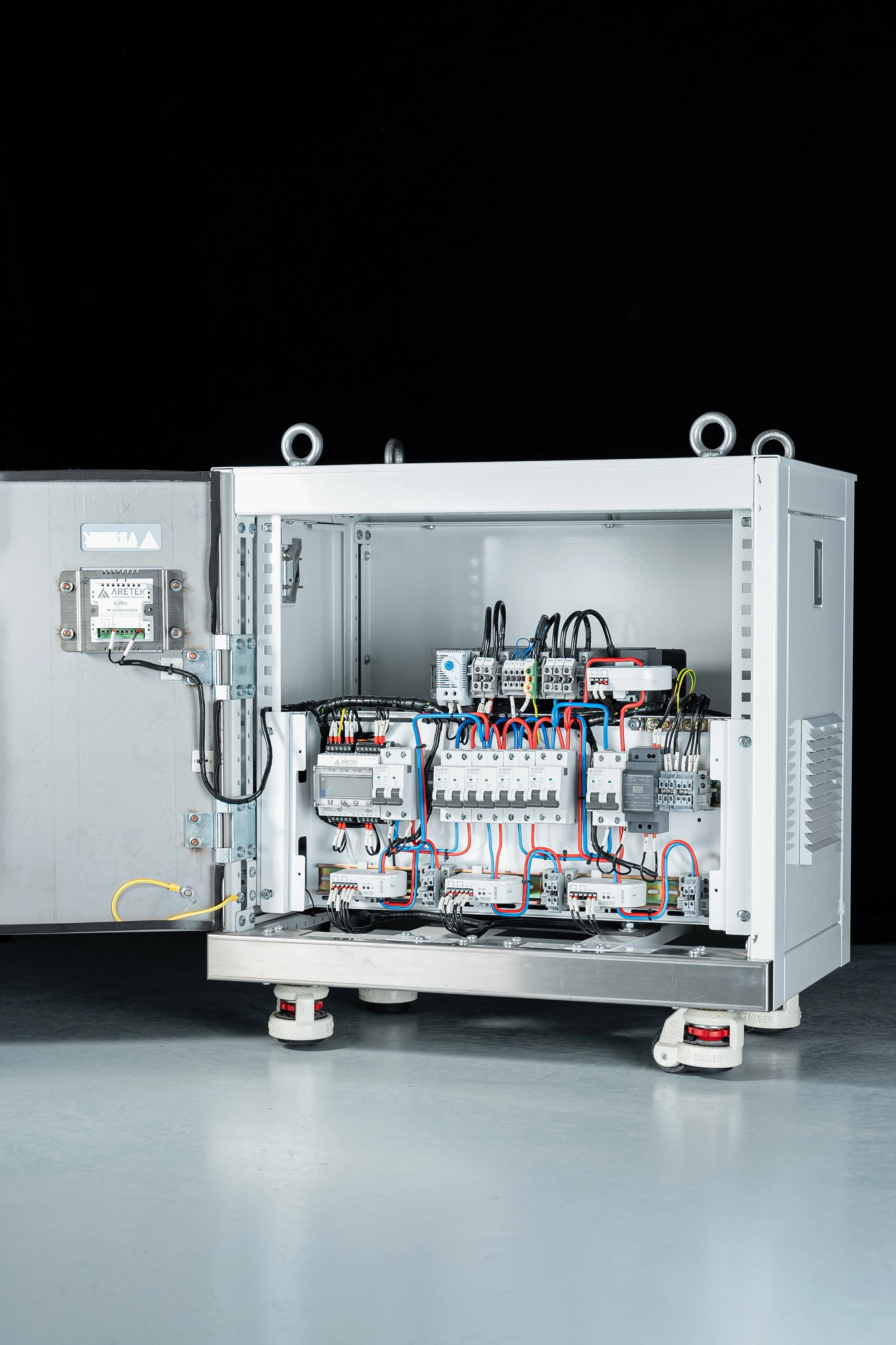
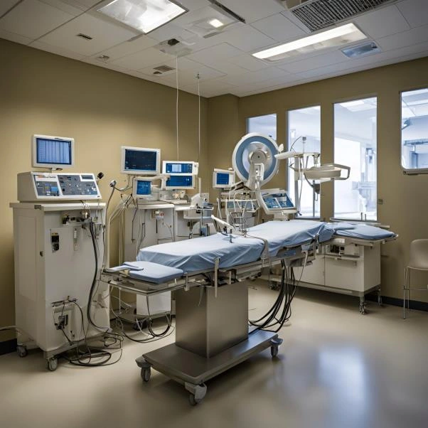
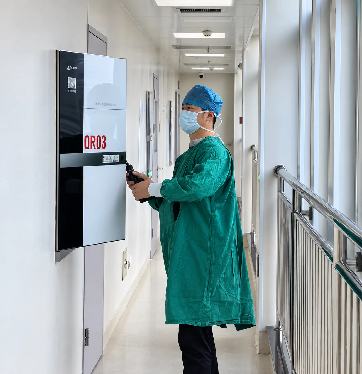
Medical sites have higher requirements for power supply continuity, fault warning, and operation and maintenance response. The solution can be used in conjunction with equipment such as ATK-MED712PLUS, and is configured with corresponding monitoring functions based on site grouping, diagnosis and treatment activities, and project design documents.
Medical Class 1 places · TN circuit
Continue to pay attention to residual current, operating status and temperature rise changes to provide a basis for loop abnormality early warning and maintenance positioning.
Medical Class 2 places · IT systems
Focus on monitoring system insulation, load and temperature status, and support continuous operation management of key circuits through hierarchical alarms.
Core monitoring and communication capabilities
Screw-free connections simplify on-site wiring, and the structural design meets the relevant installation requirements of DIN 43880.
Broadband system adaptation supports 0–1000 Hz AC and DC system monitoring.
Status visible multi-color LED intuitively displays communication status and fault alarm.
The monitoring range is 0–70 mA, and the response value setting should match the specific equipment configuration and loop design requirements.
Continuous online operation supports 7×24 hours monitoring and uses DC 24 V power supply.
The transformer and conductors should be matched according to the actual hole size, conductor outer diameter and equipment installation requirements. The wiring and installation shall be subject to the corresponding model instructions.
Temperature monitoring supports NTC temperature signal monitoring to assist in identifying abnormal temperature rises.
System communication provides RS-485 signal output for easy access to a host computer or centralized monitoring system.
Fault Analysis Model 617 equipment supports fault wave recording and Fourier characteristic analysis, which is subject to configuration.
Application scenarios and configuration principles
For different levels of medical premises, differentiated monitoring strategies are adopted for TN and IT loops. General diagnosis and treatment areas can continuously monitor the residual current and operating status of the TN loop; for key diagnosis and treatment areas that require higher power supply continuity, hierarchical alarms can be established based on IT system insulation, load and temperature monitoring.
Installation, debugging and daily operation and maintenance
Installation and wiring: Use screw-free connection method, and complete the connection of terminals, transformers and communication lines according to the equipment instructions and project drawings.
System debugging: Set the alarm threshold, communication address and monitoring parameters according to the loop purpose, and verify the alarm and upload functions.
Daily inspection: Regularly check LED status, temperature trends, alarm records and communication quality, and locate abnormal loops in a timely manner.
Record review: Combine fault recording and historical data to analyze abnormal characteristics to provide a basis for maintenance decisions.
Note: The parameters in this article are based on existing product information. The final specifications and functions are subject to the specific selection documents, product instructions and project design requirements.