Technical reference · English
Protection coordination
| Technical selection | Data and status |
|---|---|
| PC / CB | Source transfer |
| ACB · Icw | Protection coordination |
| ATMT | Bus-tie interlocks |
| UPS | Emergency supply and continuity |

Engineering application
Coordinate source monitoring, transfer interlocks and downstream protection. ATSE restores supply after a source failure; UPS supports loads whose permitted interruption is shorter than the transfer sequence.
SOLUTION INSIGHTS
ATK-CP · PC / CB
ATMT · ACB
Icu · Ics · Icw
Start with the source pair, calculated load, prospective short-circuit current and permitted interruption. PC-class ATK-CP transfers the load and requires coordinated upstream short-circuit protection. A CB-class arrangement incorporates circuit-breaker protection, whose settings must match the load duty. For motor and mixed loads, confirm the declared utilisation category for the exact frame and operating frequency. Rated current alone cannot establish making capacity, fault withstand or suitability for repeated transfer.
Define source-failure confirmation, standby-source availability, opening of the active source, the open interval and closure onto the standby source. Return requires stable normal-source conditions and its own delay; generator cooldown follows the project sequence. Motor residual voltage can require a longer open interval. Product contact-transfer time is only one part of total restoration time. Loads unable to tolerate that interval need a suitable UPS supply, coordinated with bypass and maintenance states.
For a two-incomer and bus-tie scheme, define permitted switch combinations before programming automatic transfer. An open-transition scheme must not inadvertently parallel the sources. Use both position feedback and the required electrical or mechanical interlocks; a command is not proof that a breaker moved. Before one source supplies both sections, check source, bus and feeder capacity and define any nonessential-load shedding. ATMT logic must also account for manual operation, maintenance isolation and a failed opening or closing action.
Check breaker Icu and Ics at the actual system voltage, then coordinate upstream delay with downstream clearing and the corresponding Icw duration. Do not transfer an unresolved downstream short circuit onto a healthy source. Choose pole configuration from the earthing and neutral arrangement, including generator and residual-current protection paths. Confirm that maintenance can isolate the required conductors and control supplies. Protection and interlock settings belong to one coordinated system design rather than independent device selections.
Use the single-line diagram and cause-and-effect matrix to test loss and recovery of each source, unavailable standby supply, transfer inhibition, manual mode and position-feedback failure. Record actual interruption at the load as well as controller and breaker events. Where one source carries both sections, verify load shedding and restoration order. Keep final settings, controller version, pole arrangement and test records together so later maintenance preserves the commissioned sequence.
Technical reference · English
| Technical selection | Data and status |
|---|---|
| PC / CB | Source transfer |
| ACB · Icw | Protection coordination |
| ATMT | Bus-tie interlocks |
| UPS | Emergency supply and continuity |
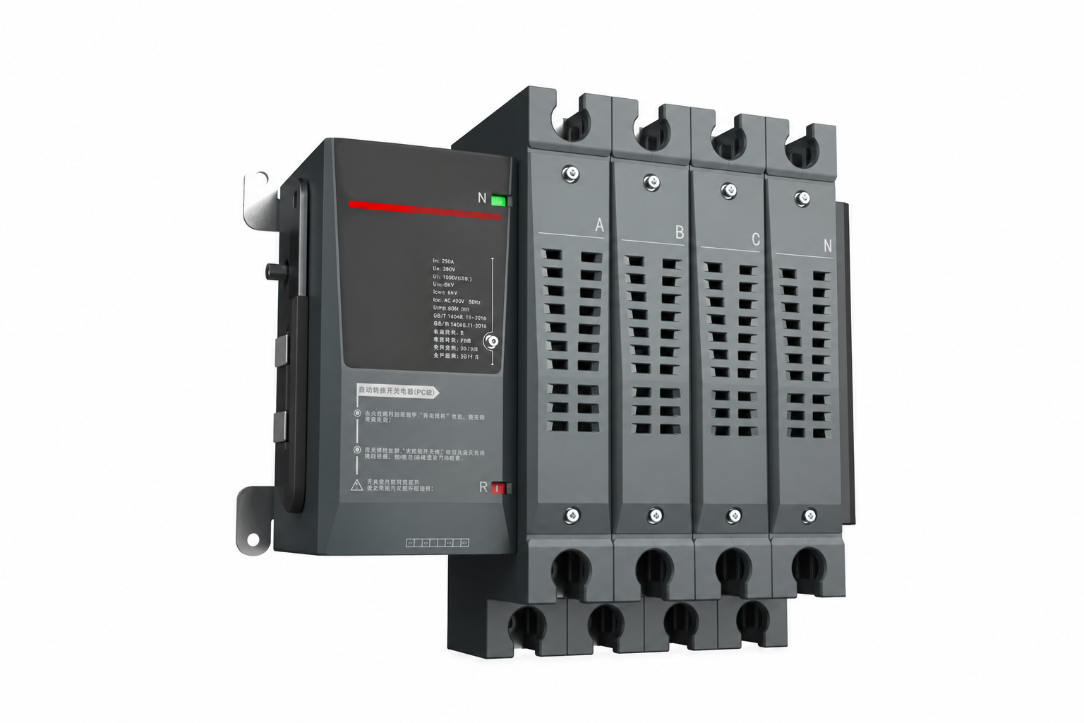
Automatic transfer switches
Automatic transfer between two power sources
This Class PC automatic transfer switch comprises the main unit, control system and connecting harness. If one source fails, the load can be transferred to the other. It provides an option for hospital, commercial-building and other supply systems; confirm transfer conditions and configuration against the load.
Automatic transfer switches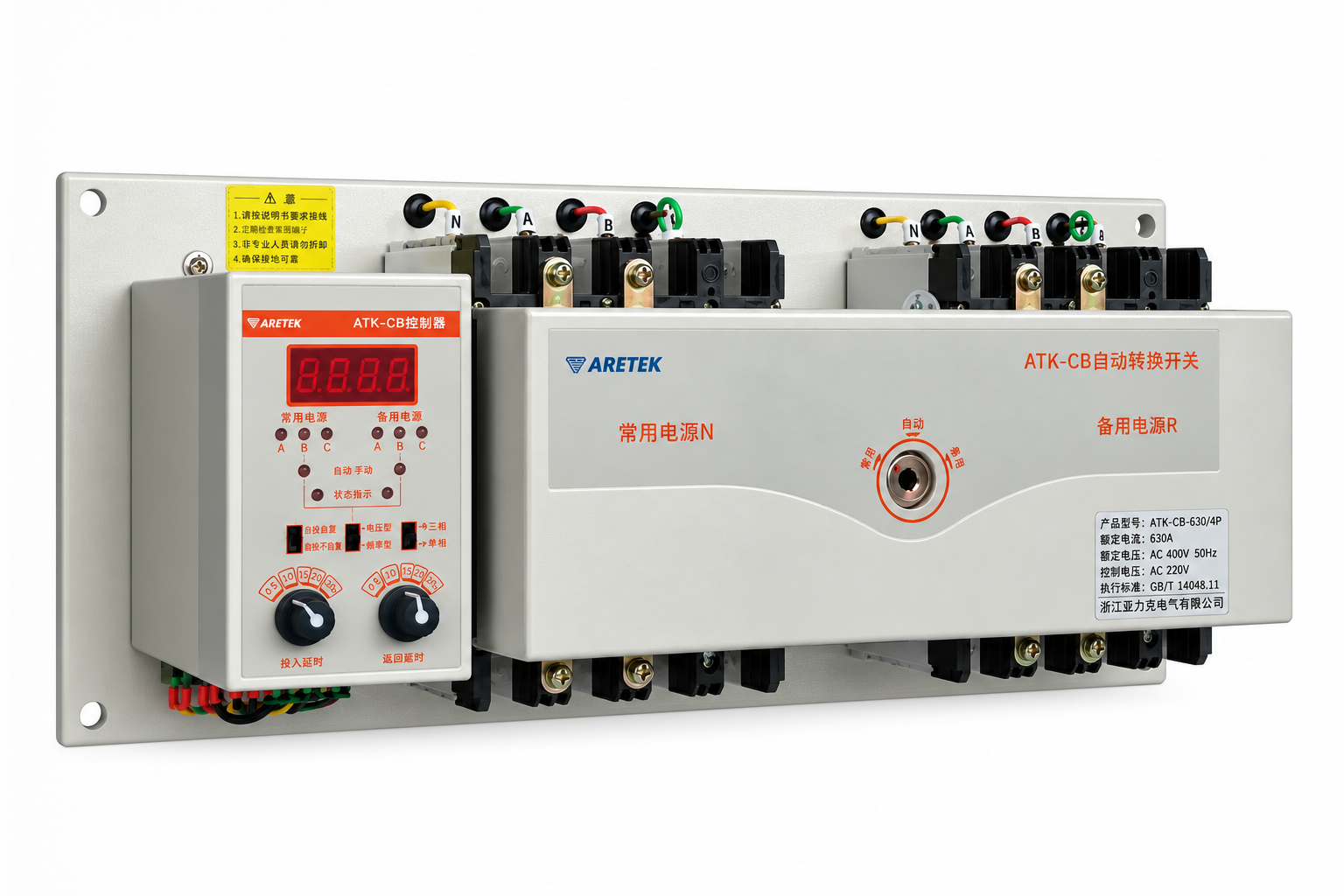
Automatic transfer switches
Configure switching for a dual-source supply
A Class CB transfer switching device for dual-source power systems. Define the supply structure and transfer requirements, then consult the product documentation and technical team to confirm functions, performance and associated equipment for the site.
Automatic transfer switches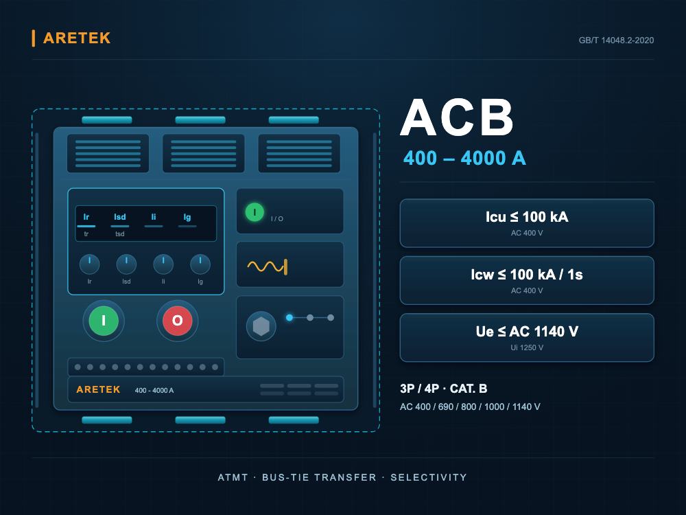
Air circuit breakers
Selective protection for main distribution
Five frames cover 400–4000 A. Compare the operating voltage, breaking capacity and short-time withstand current for each frame before coordinating incoming and outgoing protection.
Air circuit breakers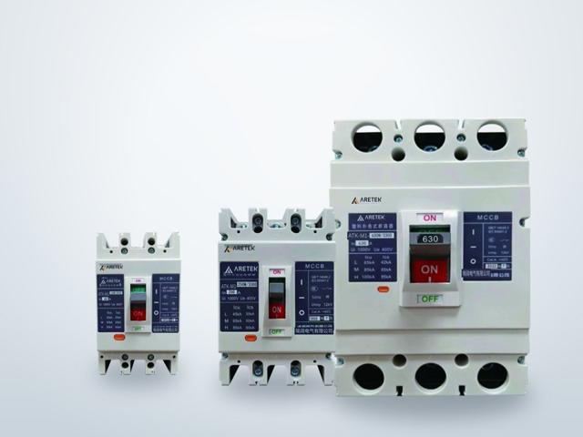
Moulded-case circuit breakers
Feeder protection with model-specific ratings
The ATK-M1 series offers seven frame sizes from 63 to 1600 A, with L, M and H breaking-capacity options. Distribution and motor-protection versions use different trip settings; the 800 A frame has no motor-protection version.
Moulded-case circuit breakers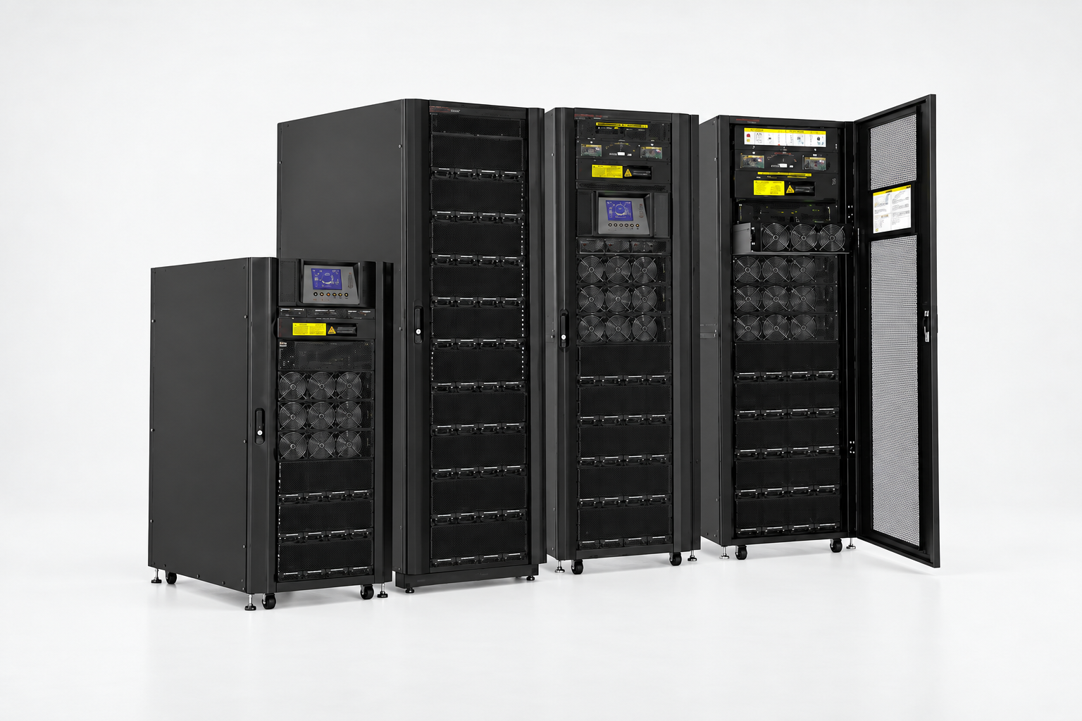
UPS systems
Configure uninterruptible power with modules and enclosures
AE-BRM9100 combines all-digital technology with a modular UPS structure. Modules and enclosures provide configuration options for uninterruptible power. Compare their documentation against the project requirements to confirm compatible combinations and the detailed supply arrangement.
UPS systemsElectrical safety. For critical environments.