Technical reference · English
Measurement interface
| Technical selection | isoEV-emb |
|---|---|
| Nominal supply | 12 V DC |
| U | 0–1000 V AC/DC |
| R | 0–10 MΩ |
| Ce | ≤ 1 μF |
| t | < 10 s |
| Data and status | UART |

Engineering application
Integrate isoEV-emb measurements into BMS state management. The module measures insulation; the BMS or VCU validates the data and decides the vehicle response.
Product visual
View full sizeSOLUTION INSIGHTS
isoEV-emb · UART
BMS / VCU
R · U · t
isoEV-emb measures insulation between the connected high-voltage system and the vehicle chassis. Its isolated UART conveys resistance, voltage and status to the BMS / VCU; vehicle software decides on permission, warnings and control actions. Contactor positions determine which battery, bus and drive sections are electrically included. DC-side and AC-side fault coverage must be verified for that topology; detecting poor insulation does not identify a particular failed component automatically.
Provide the specified isolated 12 V DC supply and define startup sequencing with the BMS. Confirm UART levels, frame format, checks and timeout behaviour against the interface document. The stated 0–1000 V AC/DC and 0–10 MΩ ranges describe measurement capability; they are not vehicle acceptance thresholds. Assess the combined capacitance of wiring, filters and motor against the ≤ 1 μF limit. The < 10 s measurement response excludes communication, decision and actuator delays.
Before enabling high voltage, check module supply, communication, self-test and data validity. During precharge and contactor changes, associate readings with the current topology and establish a valid baseline. During driving and regeneration, retain operating context with each event. During charging, coordinate the vehicle and charger monitoring responsibilities and check for interaction. Maintain separate normal, warning, confirmed-fault and monitoring-unavailable states; stale readings must not indefinitely preserve a normal indication.
Define insulation thresholds, confirmation duration, hysteresis and recovery conditions within the vehicle safety strategy. A parked vehicle, a moving vehicle and a charging vehicle can require different responses to the same confirmed fault. Log resistance, bus voltage, module status, contactor state and event time before applying the validated BMS / VCU action. Treat a communication or self-test failure separately from an insulation fault, and preserve the diagnostic record through recovery and service.
Validate positive-side, negative-side and symmetrical insulation degradation, plus representative motor-side faults. Repeat under precharge, acceleration, regeneration and charging transitions, then test capacitance limits, supply disturbances and lost communication. Capture detection and end-to-end response times separately. Freeze the module model, hardware, firmware, protocol and threshold set only after the results meet the agreed project criteria. This creates a reproducible handover configuration for vehicle development and service teams.
Technical reference · English
| Technical selection | isoEV-emb |
|---|---|
| Nominal supply | 12 V DC |
| U | 0–1000 V AC/DC |
| R | 0–10 MΩ |
| Ce | ≤ 1 μF |
| t | < 10 s |
| Data and status | UART |
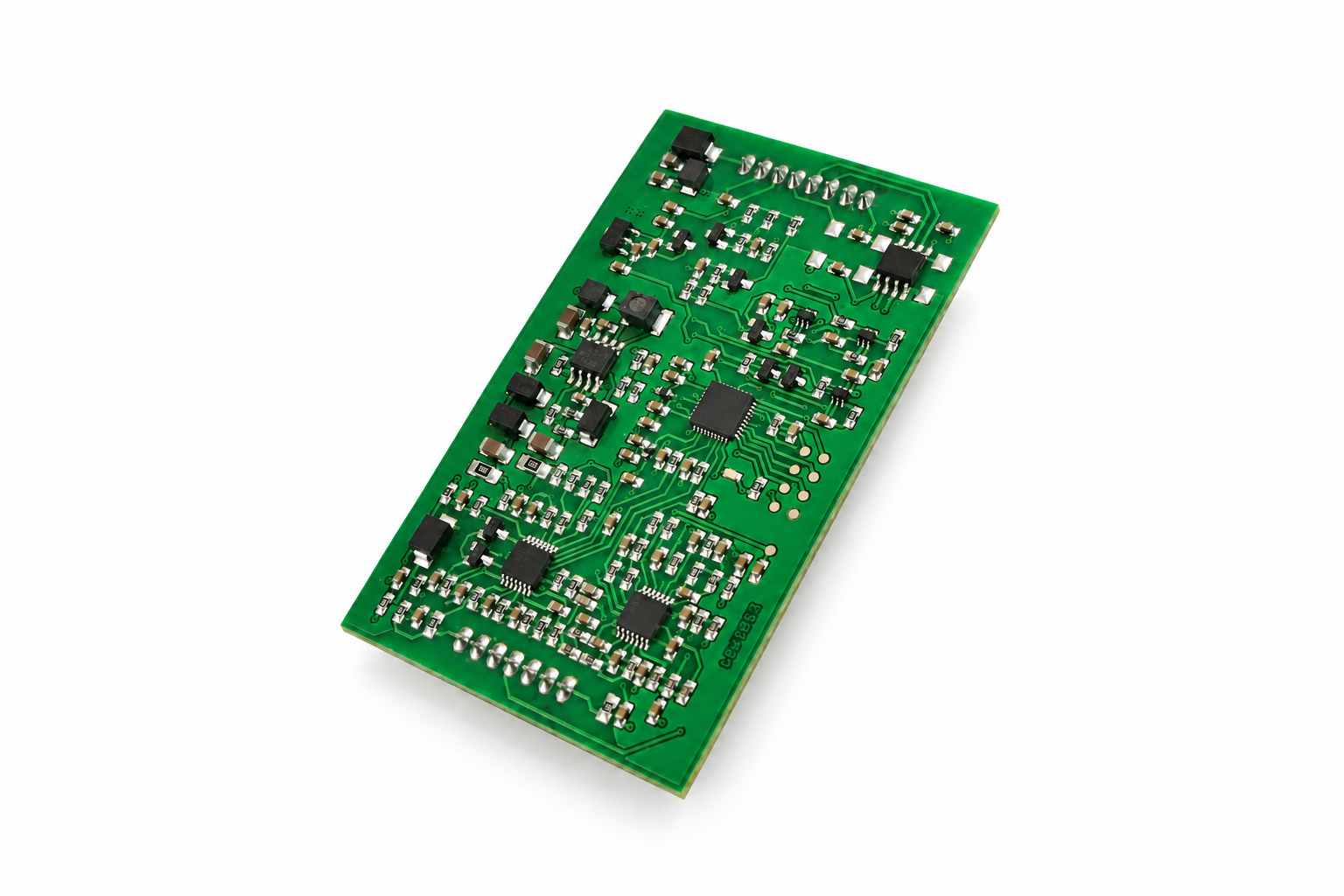
Insulation monitoring
Integrate high-voltage insulation monitoring into battery management
An embedded insulation-monitoring module for electric vehicle BMS development. It measures insulation between high-voltage components and the chassis, covering DC-side and AC-motor-side faults. An optically isolated interface transmits measurements, pre-alarms and fault information and receives host configuration commands for system integration.
Insulation monitoring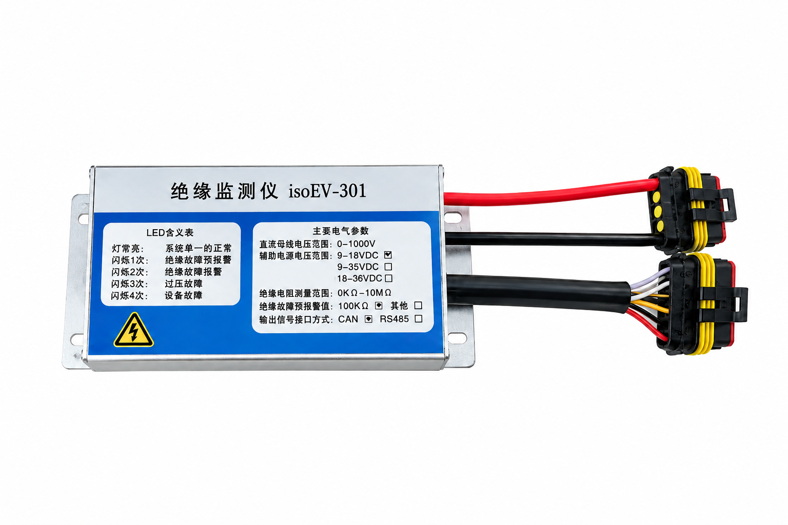
Insulation monitoring
Monitor insulation between high-voltage systems and the chassis
isoEV301 monitors insulation between an electric vehicle’s high-voltage components and the chassis reference, covering the DC side and AC motor side. It detects symmetrical and asymmetrical insulation faults. Fault-side identification is valid only during an alarm when system voltage exceeds 300 V; it is not provided for symmetrical faults. An isolated CAN interface transmits status, alarms and measurements.
Insulation monitoring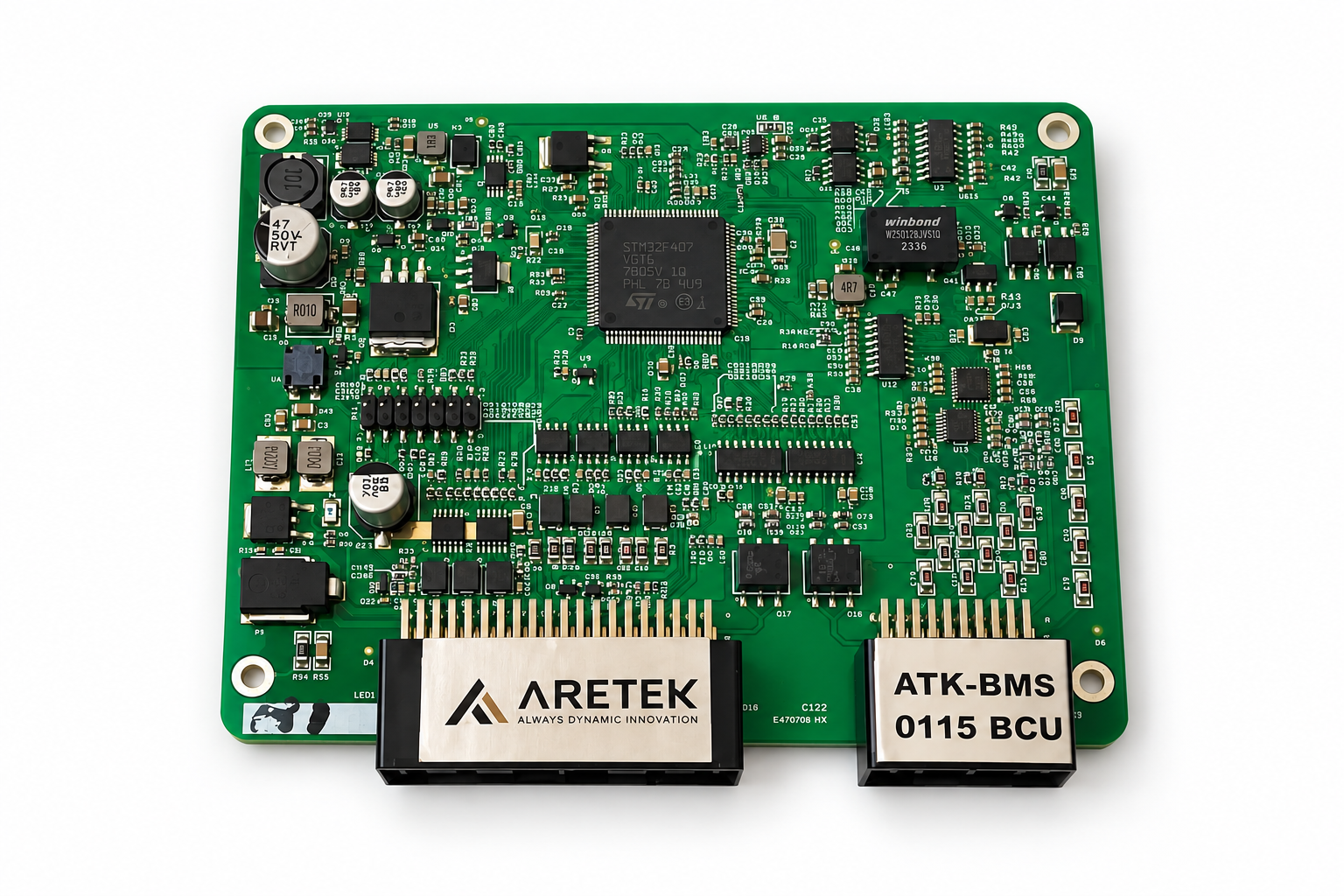
Battery management systems
Key measurements for understanding storage-battery operation
ATK-BMS0115 is part of the BMS1.0 energy-storage series. It monitors battery voltage, current and temperature to present key operating information. Select the master/slave arrangement and communications for the battery architecture and project requirements.
Battery management systemsElectrical safety. For critical environments.