01
Define the monitored network
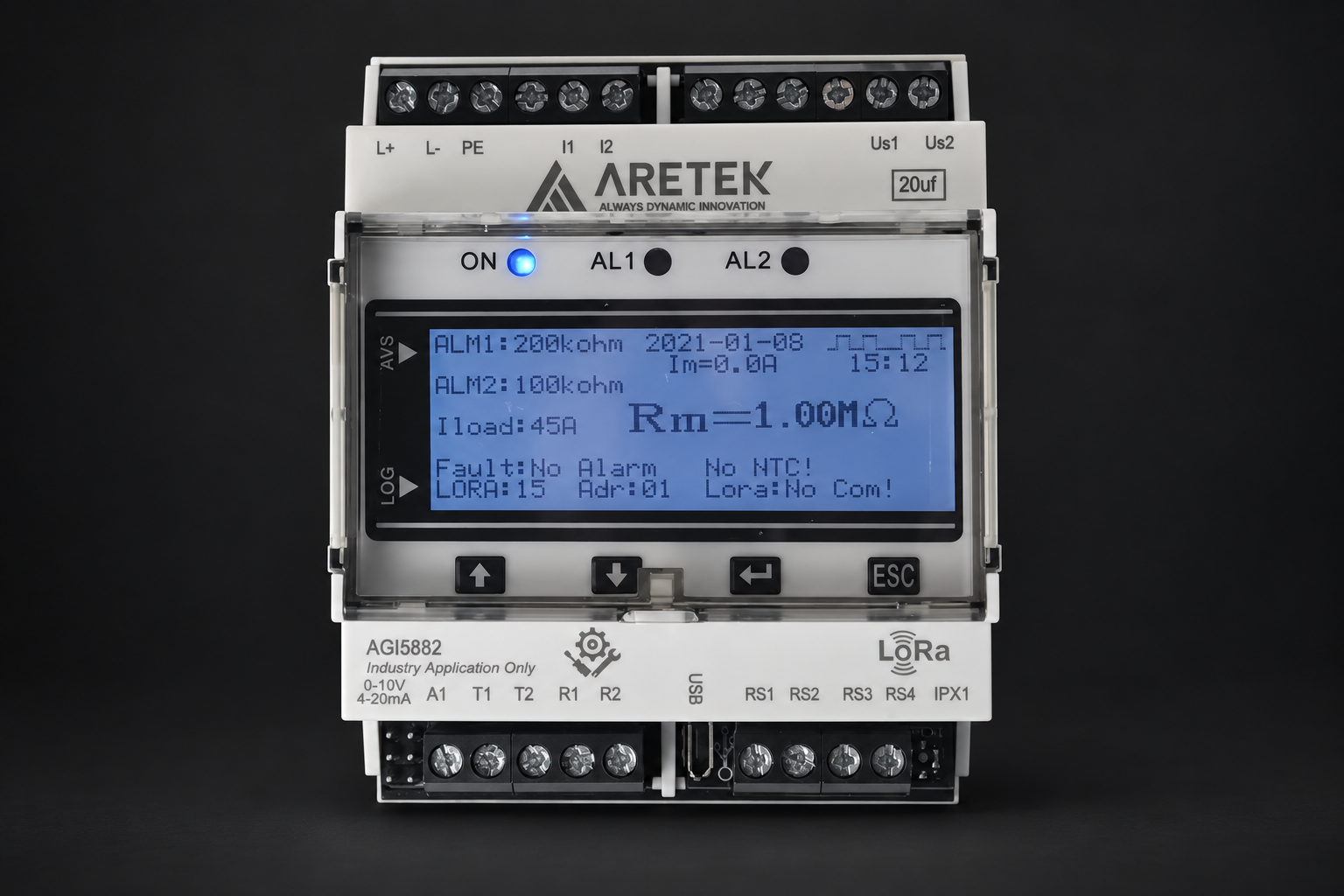
Start with the vessel single-line diagram: identify each independent bus section, its earthing arrangement, voltage and frequency, then separate propulsion, auxiliary machinery and essential services. AGI5882 insulation monitoring applies to suitable unearthed IT networks. A 440 V or 690 V bus requires a compatible coupling arrangement; a 230 V lighting circuit or 24 V DC control circuit needs its own suitability assessment. A shared application does not make every device suitable for every voltage or frequency.
02
From main switchboard to outgoing feeders
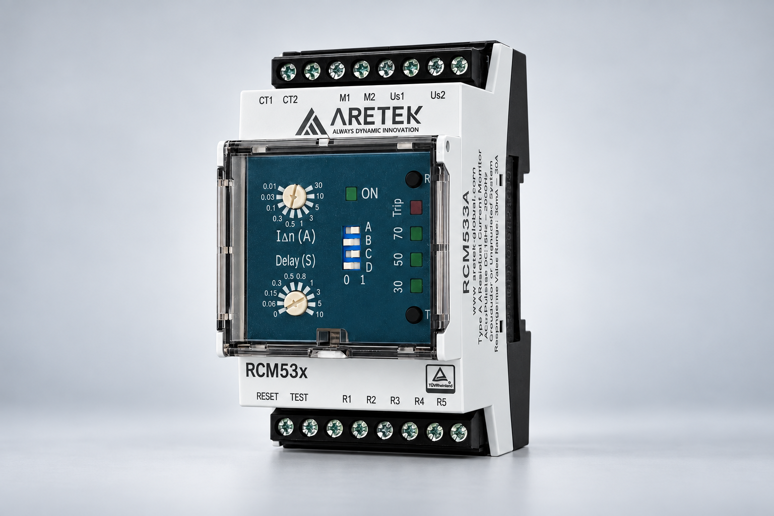
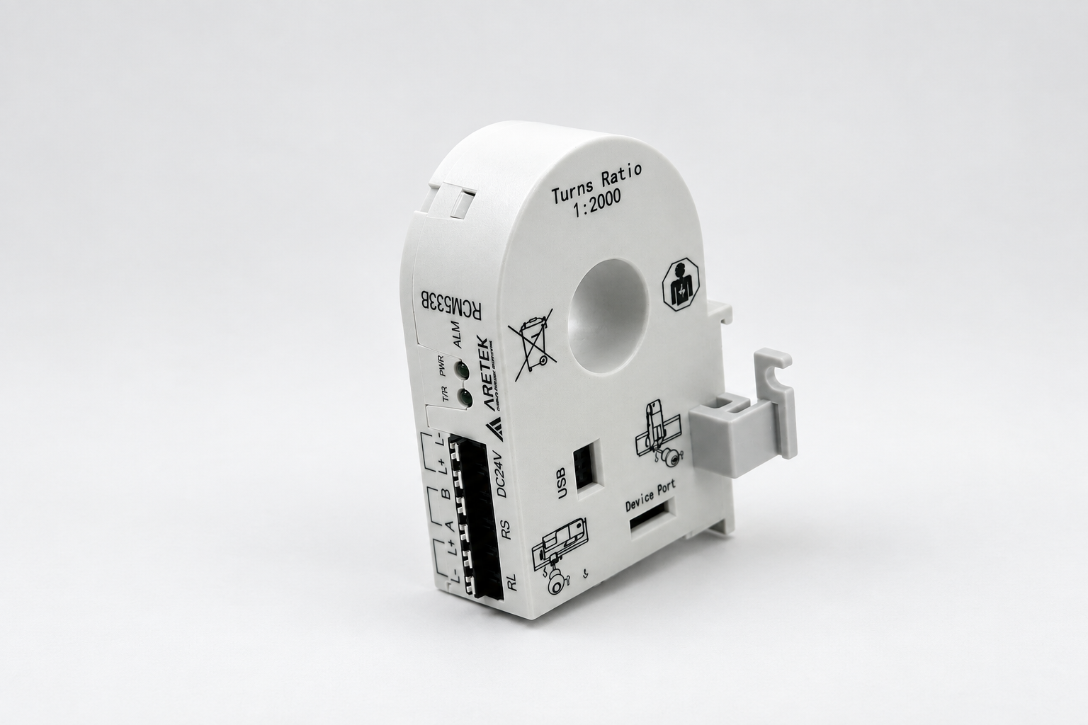
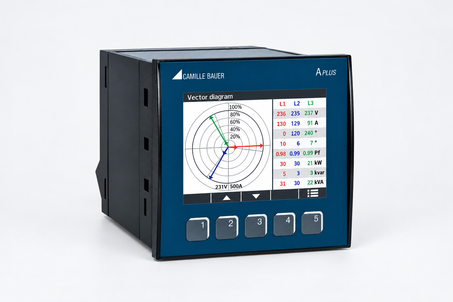
Use insulation monitoring to assess the connected IT network, and branch residual-current monitoring to associate changing leakage with individual feeders. For variable-frequency propulsion, thrusters and pumps, select RCM53xB and its sensor against the actual residual-current waveform and range. IFLS616 / IFLS617 adds circuit-level measurement and diagnostic data within its specified capability. APLUS supplies electrical measurements for incoming-feed trends. Keep every measurement associated with a cabinet and circuit identifier so maintenance can trace an alarm to the correct feeder.
03
First earth fault and bus-tie operation
In an appropriately designed IT system, the first earth fault can initiate an alarm while service continues under the approved protection strategy. Investigate it promptly: a second fault on another live conductor changes the risk. When a bus-tie closes, previously separate networks become one measurement domain; coordinate monitor operation to avoid conflicting measurement signals. Combine insulation trends, feeder measurements and compatible fault-location equipment to narrow the fault, then verify recovery after repair. Alarm acknowledgement alone does not remove the fault.
04
Emergency transfer and UPS ride-through
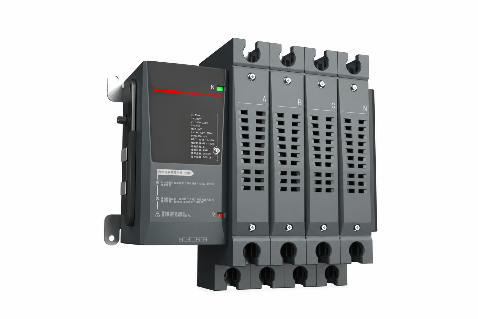
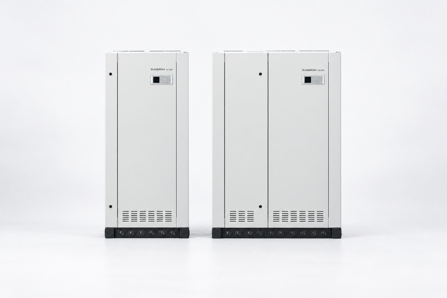
Build the supply sequence around load tolerance. Source monitoring detects loss of the normal supply, the emergency source becomes available, and ATK-CP transfers the selected circuits after the required checks. Navigation, communication and control loads that cannot tolerate this interval need a suitable UPS path. Size the UPS and battery against actual kW, kVA, starting current and required duration; check bypass and maintenance conditions as well. A fast transfer contact time alone does not establish uninterrupted power or sufficient battery autonomy.
05
Make alarms actionable in the IAS
Integrate measurements, alarm level, device status and timestamps into the IAS through the interfaces actually provided by each device. Distinguish low insulation, abnormal residual current, unavailable supply and communication failure instead of combining them into one general alarm. Retain local annunciation and hardwired signals where the design requires them. Define acknowledgement, fault clearance and recovery separately, and preserve event history so bridge and engine-control personnel see the same circuit identity and sequence of events.
06
Selection inputs and commissioning evidence
Prepare the single-line diagram, load list, prospective short-circuit currents, earthing arrangements, source frequencies and communication point list before selecting equipment. Assess vibration, humidity, salt exposure, temperature and the approvals required for the actual vessel. Commissioning should exercise separate and connected bus states, insulation alarms, feeder identification, source loss, UPS support and communication recovery. Record settings, event times and restoration conditions. These checks establish the project configuration; they do not imply that every listed component already carries marine approval.
ARETEKElectrical safety. For critical environments.